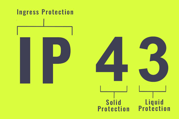
“IP” comes from standard IEC60529, it is short for “ingress protection”. IP code is a code system to indicate the degree of protection provided by an enclosure against access to hazardous parts, ingress of solid foreign object and water. The protection level is usually expressed by two numbers after IP, and the numbers are used to clarify the protection level. The first numbers (0 to 6) show the protection provided by an enclosure against access to hazardous parts or ingress of solid foreign object. The second numbers (0 to 8) show the protection provided by an enclosure against ingress of water. The IP code probes are used to verify the first numbers 1 to 4.

The IP code probes includes test probe A, test probe B, test probe C, test probe 1 and test probe 2:
1). Probes A, B, C and D are access probes to verify protection of persons against access to hazardous liver parts or hazardous mechanical parts. The probes are simulating in a conventional manner a part of a person or a tool or the tool held by a person to verify adequate clearance from hazardous parts.
2). Probes 1 and 2 are object probes to verify protection of equipment against ingress of solid foreign objects have diameter of 50mm and 12.5mm or greater. The probes are simulating a solid foreign object to verify the possibility of ingress into an enclosure. But in practise, test probe C and D are also used to verify the protection of equipment against ingress of solid foreign objects having a diameter of 2.5mm or greater and 1mm or greater respectively.
The access probes are pushed against or inserted through any openings of the enclosure with a force. For tests on low voltage equipment, a low-voltage supply (of not less than 40V and not more than 50V) in series with a suitable lamp should be connected between the probe and the hazardous parts inside the enclosure.The protection is satisfactory if adequate clearance is kept between the access probe and hazardous parts, and access probes shall not touch hazardous mechanical parts; The probe A shall not completely pass through the opening; Test probe B may penetrate to its 80mm length, but the stop face (φ50mm*20mm) shall not pass through the opening, Starting from the straight position, both joints of the test finger shall be successively bent through an angle up to 90° with respect to the axis of adjoining section of the finger and shall be place in every possible position; If adequate clearance is verified by a signal circuit between the probe and hazardous parts, the lamp shall not light.
The object probe is pushed against any openings of enclosure with a force. The protection is satisfactory if the full diameter of the probes does not pass through any opening.
| Probe code | Short description | IP grade | Test force |
| Test Probe A | Sphere: φ 50 with handle | For testing IP1X | 50N±10% |
| Test Probe B | Jointed test finger: φ 12-legnth 80 | For testing IP2X | 10N±10% |
| Test Probe C | Rod: φ 2,5 – length 100 | For testing IP3X | 3N±10% |
| Test Probe D | Wire: φ 1,0 – length 100 | For testing IP4X | 1N±10% |
| Test Probe 1 | Sphere: φ 50 | For testing IP1X | 50N±10% |
| Test Probe 2 | Sphere: φ12,5 | For testing IP2X | 30N±10% |
The test force apply to IP test probes may be different in relative product standards. One is without thruster, but it provide a connector to work with force gauge to apply appropriate force. The other is with thruster, the force can be applied directly, and force range is adjustable.
Contact: Eason Wang
Phone: +86-13751010017
E-mail: info@iec-equipment.com
Add: 1F Junfeng Building, Gongle, Xixiang, Baoan District, Shenzhen, Guangdong, China